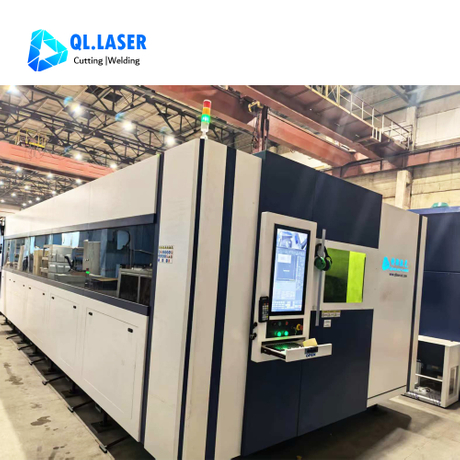
Moving between bandsaws, drills, and mills to process multiple tube profiles destroys your profit margin. Routing round, square, or asymmetrical shapes across several manual workstations heavily bloats lead times. It introduces unnecessary human error into your daily workflow. This fragmented approach forces fabrication shops to sacrifice speed just to maintain basic manufacturing flexibility. A consolidated processing center resolves this production bottleneck by handling diverse geometries in a single setup. A high-quality tube laser cutting machine can completely transform your entire production floor. It replaces multiple traditional machines instantly. This guide provides a clear, technical breakdown of how these advanced systems mechanically and digitally adapt to different pipe shapes. You will discover the essential criteria needed to evaluate machine specifications directly against your actual product mix. Production managers can use this technical data to make highly informed equipment upgrades.
Key Takeaways
Chuck configuration (2-chuck vs. 3-chuck) dictates not only which shapes can be held securely but also the volume of material wasted as scrap (tailings).
Standard profiles (round, square) require dynamic power modulation at the cutting head to prevent corner burning.
Open and complex profiles (C-channels, H-beams) demand advanced capacitive height sensing to compensate for mill-bow and material warping.
The viability of processing diverse shapes hinges heavily on CAM/nesting software capable of automated Design for Manufacturing (DFM) features like tab-and-slot cuts.
The Mechanics of Material Holding: Chuck Systems and Shape Adaptation
Pneumatic and electric rotary chucks form the foundational baseline mechanism for modern material holding. They automatically center and grip incoming materials securely. Operators do not need to perform manual jaw changes for every profile shift. This automatic adaptation keeps production moving smoothly. The machine applies precise clamping pressure based on material thickness. This prevents crushing delicate walls while firmly securing heavy structural pipes. Mechanical synchronization between the front and rear chucks ensures perfect alignment during rapid rotation.
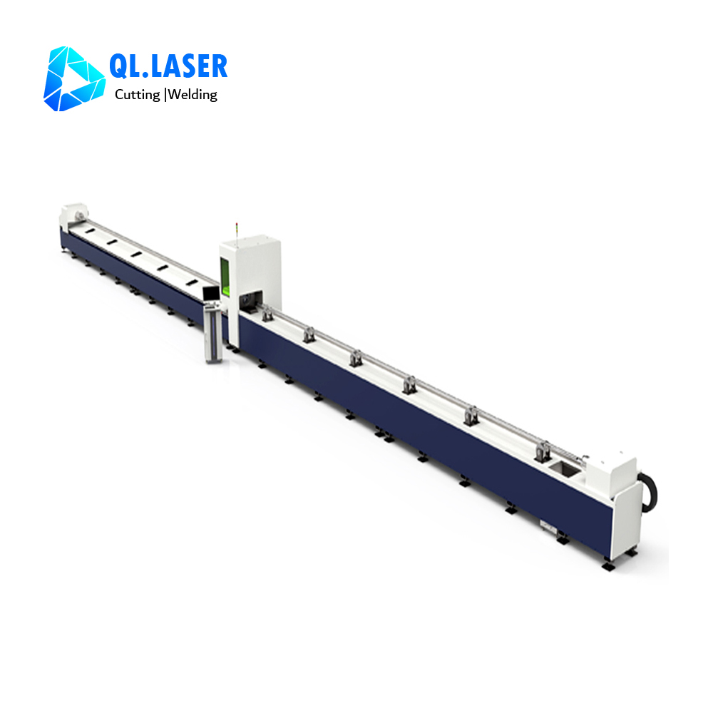
A 2 chuck tube laser cutter works best for long runs of standardized geometries. They handle symmetric weight distribution beautifully. Many entry-level and mid-range fabricators rely heavily on this configuration. However, they possess a very specific mechanical limitation. They leave a noticeably longer tailing or scrap piece. The cutting head simply cannot pass safely between the two chucks at the very end of the tube. This physical barrier forces shops to discard several inches of raw material per stick. Over thousands of cuts, this scrap volume severely impacts profitability.
Conversely, a 3 chuck tube laser cutter excels in demanding high-mix production environments. They handle exceptionally heavy or long tubes with remarkable ease. They are ideal for processing expensive materials like stainless steel or extruded aluminum where yield remains highly critical. The clamping mechanism is highly efficient and innovative. The middle and rear chucks feed the material forward. The third front chuck supports the pipe through the final cut. This creates highly desirable "zero-tailing" capabilities. It also minimizes structural vibration on asymmetrical, off-balance shapes. Superior stability ensures precise cut quality across the entire length of the tube.
Processing Standard Profiles: Round, Square, and Rectangular
Operating a dedicated round tube laser cutter involves highly specific physical dynamics. It requires continuous, high-speed 360-degree rotation. Maintaining a constant surface speed ensures clean, slag-free cuts. Round pipes offer perfectly predictable rotation paths. They represent the simplest profile to process in any fabrication shop. The focal distance between the laser nozzle and the material surface remains perfectly uniform. This stability allows for maximum cutting speeds and flawless edge quality. You can process high volumes of round piping with minimal intervention.
Processing flat-sided profiles introduces unique physical obstacles. A square tube cutting machine constantly faces what engineers call "The Corner Problem." Unlike round tubes, the cutting head must rapidly adjust its vertical Z-axis height. This aggressive movement happens exactly as flat sides transition into sharp corners. The chucks spin the square profile, causing the corner to swing outward toward the cutting head. Similarly, a rectangular tube laser cutter must manage highly uneven rotation speeds. The wider flat sides take longer to pass under the beam than the narrow sides.
To resolve this complex geometry challenge, modern equipment uses dynamic power modulation. The machine automatically reduces laser power and travel speed at the corners. Heat builds up rapidly in sharp corners. Too much power causes "corner blowout" or severe burning. Once the cutting head clears the sharp corner, it instantly accelerates back to full speed on the flats. This intelligent modulation protects the structural integrity of your parts. It guarantees sharp, clean corners without sacrificing overall cycle times. Operators rely on advanced software algorithms to calculate these micro-adjustments automatically.
Handling Complex and Open Profiles (Angles, Channels, and Beams)
Open profiles like C-channels, angle iron, and H-beams require specialized handling techniques. Securing these asymmetrical shapes safely is paramount for accurate processing. Specialized chuck jaws or adjustable digital clamping forces prevent the jaws from crushing thin-walled open profiles. They maintain essential concentricity throughout the entire cutting cycle. Asymmetrical shapes inherently create uneven weight distribution during rotation. The machine must counteract this centrifugal force to prevent dangerous vibrations. Heavy-duty servo motors provide the necessary holding torque to keep these awkward shapes perfectly stable.
Raw materials rarely arrive perfectly straight from the steel mill. Structural steel frequently suffers from mill bow, warping, or axial twist. You must account for these harsh material imperfections during automated processing. The cutting head utilizes advanced capacitive sensors to map the actual topography of the laser pipe cutting machine material in real-time. The sensor continuously measures the micro-capacitance between the copper nozzle and the grounded metal tube. It adjusts the focal length on the fly as the material bows upward or drops downward. This instantaneous reaction prevents costly head collisions. It also maintains strict cut tolerances despite poor material quality.
However, we must transparently acknowledge basic tolerance realities. An advanced machine cannot magically fix everything. Severe material twisting may still cause part-accuracy failure despite active sensor compensation. If a structural beam twists drastically over its length, the cut features will misalign during downstream assembly. Operators must establish clear raw material standards before loading heavily warped beams. Quality control begins at the loading rack, not just at the cutting head.
The Role of 3D CAM Software in Multi-Shape Fabrication
Physical capability means very little without intelligent software driving it. You need robust 3D CAM software to unwrap complex solid models into machine-readable G-code. This digital translation unlocks the true operational potential of your equipment. Older 2D software simply cannot handle the complexities of intersecting pipes or contoured bevels. Modern 3D suites visualize the entire tube length, preventing mechanical collisions before they ever happen.
Smart design and Design for Manufacturing (DFM) implementation become fully automated. This advanced software introduces highly beneficial structural features for your fabrication process:
Generating precise bend reliefs on rectangular tubes automatically.
Programming self-fixturing features across complex intersecting shapes.
Creating secure tab-and-slot or dovetail joints for rapid downstream assembly.
Mating a round pipe flawlessly to a square structural frame.
Adding precise weld-prep chamfers directly into the cutting path.
Nesting efficiency heavily dictates your ultimate profit margins. Modern software calculates the most efficient mix of parts across a single length of complex pipe. It analyzes part geometry to maximize material yield and drastically reduce scrap. It groups identical parts together and utilizes common-line cutting techniques where possible. A single laser cut separates two distinct parts simultaneously. This strategy slashes cycle times and minimizes consumable gas usage.
Evaluation Framework: Selecting the Right Machine for Your Production Mix
Choosing the right equipment requires a thorough volume versus mix analysis. If 90% of your production is standard round tube, a basic 2-chuck machine proves highly profitable. It requires lower upfront investment and delivers rapid cycle times. If your mix includes heavy structural channels, varying sizes, and exotic alloys, you require a different approach. A 3-chuck system becomes strictly necessary. You will also need heavy-duty loading automation to handle the diverse weight profiles safely.
Assess the manufacturer's spec sheet critically. Look far beyond the basic maximum diameter capabilities. You must evaluate the maximum weight per foot limits. Spindle load capacity dictates whether you can actually spin a heavy steel beam without stalling the motors. Verify the chuck pass-through limits to ensure your largest profiles can feed through the rear chuck smoothly.
Consider your factory's automation footprint carefully. How are different shapes loaded efficiently? Bundle loaders work exceptionally well for large volumes of round and square tubes. They drop one tube at a time into the feeding mechanism. However, open profiles or very large structural shapes often require distinct step-loaders. Sometimes they need completely custom material handling integrations to prevent interlocking during the feeding cycle.
Chuck Configuration Comparison
| Feature | 2-Chuck System | 3-Chuck System |
| Best Application | High-volume standard profiles | High-mix, heavy, or long tubes |
| Tailing Scrap | Noticeable tailing loss | Zero-tailing capability |
| Weight Distribution | Symmetrical balance preferred | Handles asymmetrical shapes well |
| Vibration Control | Moderate stability on long parts | Superior stability across all lengths |
Before making a purchase, take a practical next step. Send a challenging, multi-shape nesting file to the manufacturer. Request a detailed time-study and a physical sample cut rather than relying solely on brochure speeds. Ensure you involve a trusted tube laser cutting machine partner during this evaluation phase.
Actionable Next Steps for Evaluation
Audit your current production mix to determine dominant pipe shapes and maximum weights.
Calculate your average scrap percentage to justify expensive zero-tailing upgrades.
Send a challenging 3D CAD file to manufacturers for a real-world time study.
Test the CAM software interfaces for ease of multi-shape nesting.
Verify factory floor space for bundle loaders versus specialized step-loaders.
Conclusion
The ability to fabricate diverse profiles seamlessly relies on a highly integrated triad. You need adaptable chuck mechanics, real-time capacitive sensor feedback, and intelligent 3D nesting software working in perfect unison. Master this combination to eliminate severe production bottlenecks.
Make your final equipment decision based on actual, historical material mix data. Prioritize raw material yield and the outright elimination of secondary downstream processes. Eradicating manual drilling, coping, or welding preparation allows you to calculate a highly accurate return on investment.
Take immediate actionable steps moving forward. Audit your top ten most manufactured parts to identify your exact shape constraints. Review your current scrap volumes generated by traditional bandsaws. Prioritize machines offering robust capacitive sensing if your workflow involves heavily warped structural steel. Empower your engineering team to adopt DFM principles today.
FAQ
Q: Does a tube laser cutter require different fixtures for every pipe shape?
A: No, modern self-centering chucks adapt automatically to standard shapes within their designated diameter range. They adjust clamping pressure dynamically without manual intervention. Extreme custom profiles or highly asymmetrical extrusions may occasionally require specialized jaws, but standard structural shapes do not.
Q: Can a tube laser cut highly reflective materials like aluminum or copper pipe?
A: Yes, modern fiber laser sources handle highly reflective metals quite effectively. However, they require specific power modulations and cutting gas parameters compared to standard carbon steel. Using high-pressure nitrogen as an assist gas prevents oxidation and avoids dangerous back-reflection damage to the internal optics.
Q: What is the minimum and maximum wall thickness a tube laser can process?
A: Processing capabilities generally range from thin-wall 0.040" tubing up to 1" thick materials, depending heavily on the laser's wattage. It is important to note that corner profiles on square and rectangular tubes dictate maximum thickness capabilities much more strictly than standard round tubes.