Continuous coil feeding completely transforms modern metal fabrication. It removes sheet-switching downtime entirely. However, it introduces unique mechanical variables into your production line. Two major factors dominate this continuous process: material tension and kinetic alignment. Fluctuating tension causes severe material warping. It also creates inconsistent focal lengths during cutting. Furthermore, lateral misalignment leads to edge defects. You might experience internal stress release issues. Sometimes, it even causes catastrophic laser head collisions. This article provides a verifiable framework for process optimization. We aim to help production managers synchronize the uncoiler and the cutting head perfectly. By optimizing these mechanical elements, you ensure maximum material yield. You also protect expensive optical tooling investments for the long term.
Key Takeaways
Precision Requires Synchronization: Achieving ±0.1mm repeatability relies on closed-loop communication between the servo feeder and the laser's CNC controller.
Thermal & Mechanical Pre-conditions: Accurate alignment cannot be measured on a cold machine; a 30-minute thermal warmup prevents metal contraction/expansion errors.
Tension Eradicates Internal Stress: Optimizing the uncoiler's back-tension and the leveler's roller configuration prevents thin-sheet deformation (common in 0.6–1.2mm HVAC materials).
Vendor Selection Matters: A reliable Coil Feeding Laser Cutting Machine manufacturer will engineer native integration between the feeding line and the optical system, rather than retrofitting disparate parts.
The Business Cost of Sub-Optimal Tension and Misalignment
Scrap rates significantly impact your bottom line. Traditional stamping typically generates 8% to 12% material waste. A fully optimized Coil Feeding Laser Cutting Machine drops this waste to just 2% to 3%. It achieves this massive reduction through zero-gap nesting. However, this efficiency only occurs if lateral alignment holds perfectly true. The material must remain aligned over thousands of meters of continuous feed.
Next, consider optical degradation. Poor tension control causes the metal web to sag. Sometimes the material bounces across the cutting bed. The auto-focus cutting head must constantly compensate for these vertical deviations. This continuous micro-adjustment accelerates wear on your z-axis drives. It drastically increases the risk of expensive nozzle collisions.
You must also master edge quality defect identification. Operators should assess physical symptoms of misalignment regularly. Look for asymmetrical burrs along the cut path. Watch for unilateral rough edges or inconsistent kerf widths. These defects rarely signal optical failures. Instead, they indicate the material drifting off parallel during feeding.
Production Method
Average Scrap Rate
Tooling Wear Factor
Material Yield Optimization
Traditional Stamping
8% - 12%
High (Physical dies)
Fixed gaps required
Coil Fed Laser Processing
2% - 3%
Low (Optical path only)
Zero-gap nesting enabled
Engineering Criteria for Optimal Coil Tension Control
Optimal coil tension demands precise engineering controls. You must manage several mechanical zones perfectly to ensure flawless production.
Uncoiler Back-Tension Optimization
Evaluate hydraulic expansion mandates carefully before operation.
Determine the necessity of motorized support arms. These arms prevent heavy coil sagging and erratic unwinding.
Define the role of continuous tension feedback loops. They prevent dangerous "whipping" effects when the machine executes high-speed flying cuts.
Leveling and Internal Stress Relief
Flattening goes far beyond visual appearance. Releasing the coil's residual curvature is mandatory. It maintains a perfectly flat focal plane under the laser beam. Highlight the necessity of a multi-roller configuration. Industry standards dictate three-up, three-down six-roll systems. These advanced systems require precise micro-adjustment capabilities to eliminate structural stress.
Servo Feeder Calibration
Calibrate your servo feeder accurately before cutting begins. You must configure multi-roller clamping pressures for different surfaces. Proper pressure prevents slip on oiled materials. Conversely, you must avoid inducing surface marring on sensitive materials. Aluminum and stainless steel require delicate handling and specific roller durometers.
Proper alignment prevents costly errors. Follow this verifiable framework for mechanical and optical alignment routines.
Phase 1: Thermal Stabilization
Never measure alignment on a cold machine. You must mandate a 30-minute machine warmup before any alignment tasks. This crucial step neutralizes thermal drift in the gantry. It also stabilizes the optical path components against expansion.
Phase 2: Lateral Material Alignment
Verification requires precision mechanical instruments. Use digital calipers alongside edge-detection sensors. Verify the coil edge is perfectly parallel. It must match the machine's X-axis travel exactly over the entire bed length.
Phase 3: Optical Concentricity Testing (The Tape Test)
Follow these exact steps for the tape test validation:
Install a specific test nozzle onto the cutting head (e.g., 1.5mm).
Apply 2-3 layers of transparent or masking tape to the nozzle. Never use a single layer, which poses a severe fire risk.
Set your piercing power to a safe 15% to 30% range.
Trigger a short pulse of approximately 80ms to verify beam concentricity.
Use an Allen wrench to adjust the coaxial screws. Stop when the burn mark sits perfectly centered.
Software Synchronization and Adaptive Feedback
Modern systems rely heavily on intelligent software. Closed-loop communication bridges the gap between hardware and software. The laser's CNC controller must react dynamically during processing. It needs to limit cutting speeds automatically if the servo feeder detects a tension drop. It also triggers corrective actions during micro-slip events.
Adaptive edge finding enhances precision even further. Utilize the laser's capacitive height sensor. Combine this sensor reading and automatic edge-finding routines. They work together to compensate for micro-deviations. Coils rarely possess perfect straightness. The software corrects these errors before initiating the nesting program.
Furthermore, always adjust parameters based on material behavior. Tension and alignment behaviors change dramatically by material type. For instance, 3mm carbon steel requires distinct feeding torque. It uses specific gas pressure, typically Oxygen around 15 bar. Highly reflective, heat-sensitive 1.2mm Aluminum demands completely different parameters.
Material Type
Thickness
Assist Gas
Gas Pressure
Feeding Torque Consideration
Carbon Steel
3.0mm
Oxygen
~15 bar
High torque, steady feed rate
Aluminum (Reflective)
1.2mm
Nitrogen / Air
~10 bar
Medium torque, anti-marring active
Galvanized Steel (HVAC)
0.8mm
Air
~8 bar
Low torque, high-speed adjustment
Evaluating a Coil Feeding Laser Cutting Machine Manufacturer
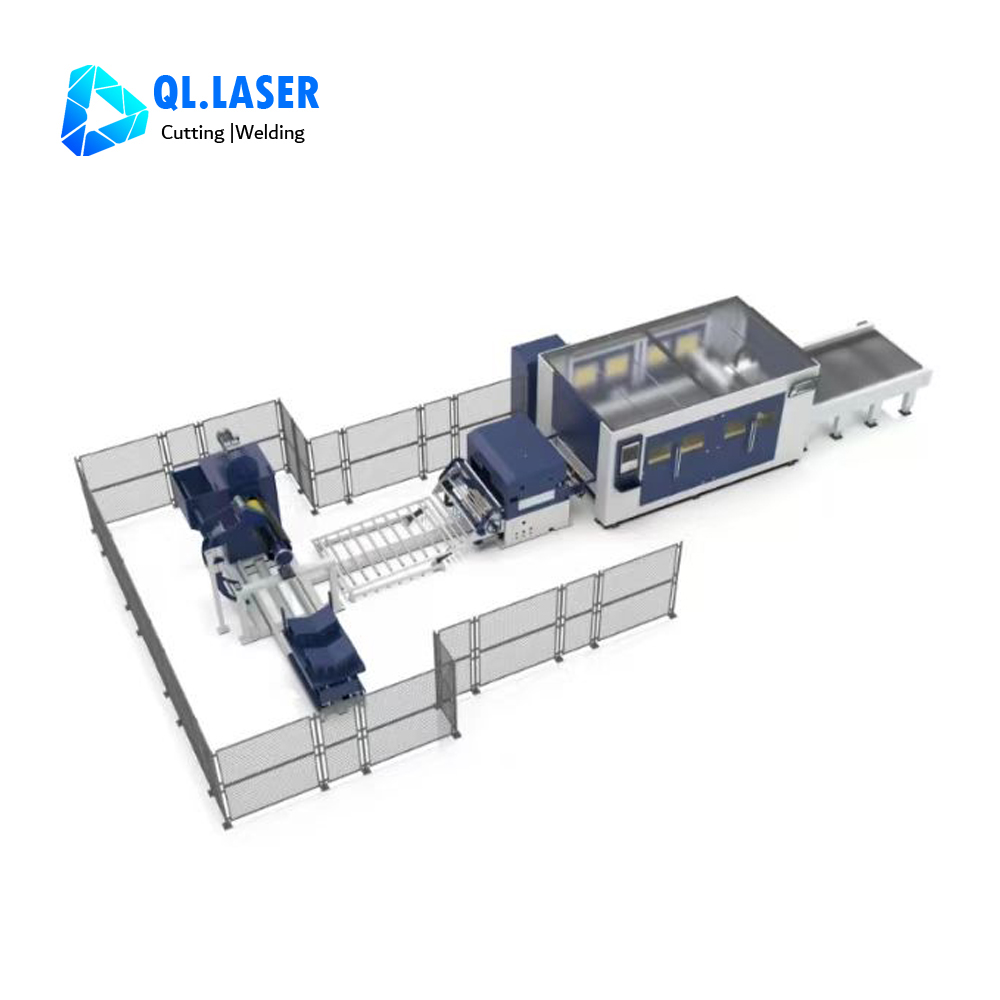
Choosing the right equipment partner dictates your ultimate success. You must evaluate integration versus bolt-on solutions carefully. Assess how the manufacturer builds the uncoiler and leveler. Determine if they unify the laser as a single PLC system. Some vendors simply bolt a third-party feeder to a standard flatbed laser. Unified systems offer vastly superior error-handling capabilities. You need seamless communication across all structural modules.
Scalability for material thickness matters immensely. Does the manufacturer offer distinct configurations for varying jobs? Thin sheets require anti-slip toothed rollers. Conversely, thick plates demand heavy-duty hydraulic decoilers. A top-tier Coil Feeding Laser Cutting Machine manufacturer provides these scalable options natively.
Finally, review their Service Level Agreements (SLA) and operator training. Check for verifiable post-sale support. Support must focus on alignment SOPs and tension calibration training. Proper training ensures your operators can maintain ±0.1mm tolerances consistently. They should achieve this without constant vendor intervention.
Conclusion
Optimizing tension and alignment remains a continuous interplay. It is never just a one-time setup task. You must constantly balance mechanical leveling, servo control, and optical precision. Resolving these variables unlocks actualized throughput. It bridges the gap between theoretical speeds and real-world production.
We encourage buyers to audit their current scrap rates immediately. Demand live tolerance demonstrations on your specific material thicknesses. Consult a specialized equipment manufacturer for a truly integrated system. Taking these actions protects your tooling investments and maximizes production yield.
FAQ
Q: How often should optical alignment be checked on a continuous coil-fed laser?
A: You should establish strict preventative maintenance schedules. Perform weekly checks for high-volume 24/7 production lines. Additionally, operators must check alignment immediately following any material crash or nozzle collision.
Q: What causes the metal sheet to warp during the laser cutting process despite a good leveler?
A: Warping results from a combination of unrelieved internal coil stress and excessive thermal input. Using wrong laser parameters or inadequate assist gas cooling causes this issue. Synchronizing your cutting speed and material tension prevents thermal buildup.
Q: Can a coil feeding system maintain the same accuracy as a traditional flatbed laser?
A: Yes. Modern systems utilize closed-loop servo feeders and active edge-detection software. These advanced coil-fed systems consistently achieve ±0.1mm positioning accuracy. They match or exceed the precision of traditional manual loading methods.