I.Robot Welding Description:
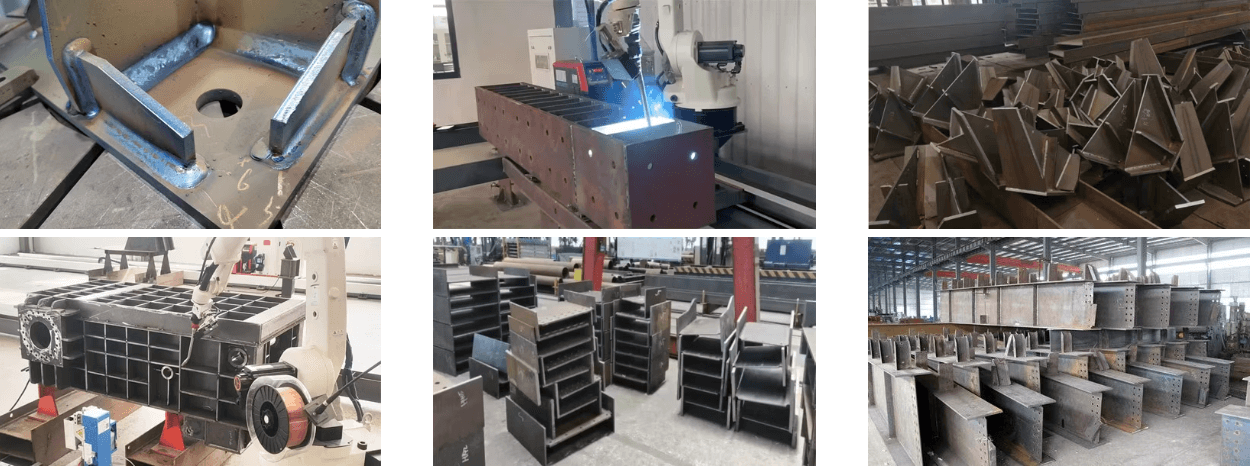
1.Strong applicability, capable of welding large components such as U-rib plates and bridge plate units;
2.Wide working area, capable of welding various long and curved welds;
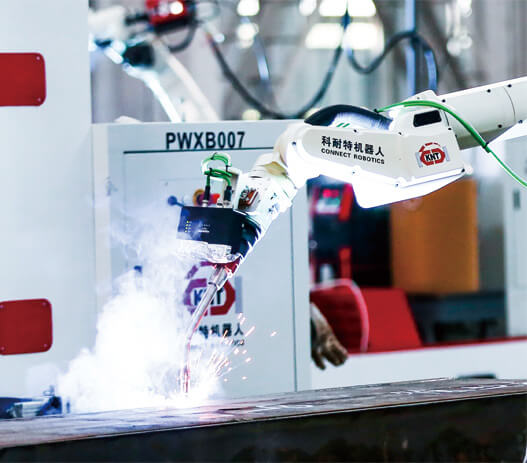
3.Single robot collaborative operation effectively improves welding efficiency, reduces welding deformation, and ensures welding quality;
4.By cooperating with the gantry walking track, it is possible to achieve simultaneous welding and handling of workpieces, thereby improving production efficiency.
5.The software can be operated in a foolproof manner after 1-2 days of training, and there is no need for manual intervention throughout the entire process after loading, greatly reducing the skill requirements for operators.
II.Robot Welding Parameters:
| Content | Parameter Range | Unit | Remarks |
| Degrees of Freedom (Axes) | 9 | / | / |
| Required Ambient Temperature | -10~45 | ºC | / |
| Maximum End Load | 6 | Kg | / |
| Recommended Floor Space | W8000*L20000*H2000 | mm | / |
| Peak Total Power | 60 | kW | / |
| Rated Input Voltage/Frequency | 380+/-10% | V | Three-phase |
| Rated Input Frequency | 50 | Hz | / |
| Floor Space | 10000*22000 | mm | / |
III. Robot Welding Advantages:
 | Robot Integrated Drive and Control System
1. Comes with a built-in robot drive system, revolutionizing the traditional teaching programming system.
2. The software automatically plans the robot's motion trajectory and adjusts the welding posture.
3. Software planning allows for intelligent obstacle avoidance by the robot.
4. Equipped with collision detection and monitoring. |
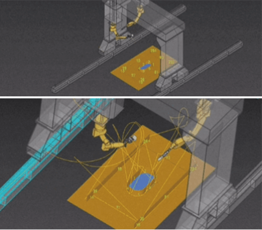
Digital Twin System
1. The scene model presents a 1:1 replication of the physical object-what you see is what you get.
2. Operation through the computer interface, with the physical object following movements. 3. Scene-generated trajectory, one-click command, and welding can begin. 4. Real-time communication, integration of virtual and physical, command execution. | 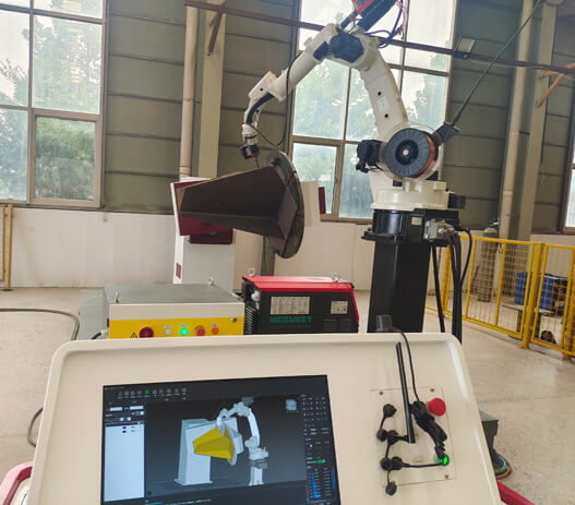 |
 | No-Teaching, No-Programming
1. Automatic Programming · Smart and Convenient: Import the 3D model of the workpiece, automatically recognize and extract welding seam information. You can edit the welding seam simply by clicking the model, reducing operational difficulty, allowing staff to get started easily.
2. Process Commands · Rapid Deployment: Corner welds, intermittent welding, multi-layer and multi-pass commands can be selected with one click.
3. Vision Guidance · Automatic Path Planning: Using line laser scanning, the robot quickly locates the start and end positions of the welding seam. |
Built-in Welding Process Library
1. Blueprint Import - Parametric Modeling: Import 3D blueprints of the workpiece. Supports exporting and importing workpiece blueprints with already edited welding seams. Parametric modeling for similar types of workpieces, such as gussets and I-beams.
2. Weld Seam Editing: Select weld edges to batch-generate weld seams, break over weld holes, and continuously weld edges. Choose welding processes according to the weld seam (multi-layer and multi-pass, upward vertical corner weld).
3. Simulation Check: Verify whether the running trajectory is reasonable, or if there is any interference. Ensure that the welding angle satisfies the welding process. | 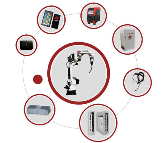 |
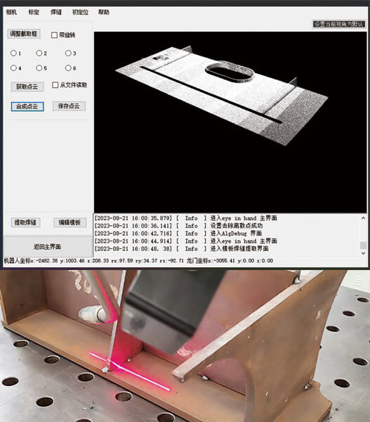 | Visual Positioning and Tracking Module
1. 3D Camera Initial Positioning:
Captures a large area of 2m x 2m; multiple photos can be stitched together for point cloud data, no worries about larger workpieces.
The photographing accuracy has an error margin of ±0.5mm, fully meeting welding precision requirements.
2. Line Laser Guidance Module:
Actively collects welding seam information and processes it in real-time, analyzing the collected images to acquire the welding seam's position, which can be used to correct the welding trajectory or guide welding.
3. "Eye-in-Hand"-Compound 3D Camera:
Solves imaging challenges in complex working conditions through the "eye-in-hand" system:
(1). Large field of view, high precision, 3D.
(2). Accurately reflects the position and posture of the workpiece, with image capture to result output time being less than one second.
(3). Precise positioning prevents collisions during the welding process.
(4). Full graphical interface operation-no prior robot operation experience required, easily completing the entire workflow. |
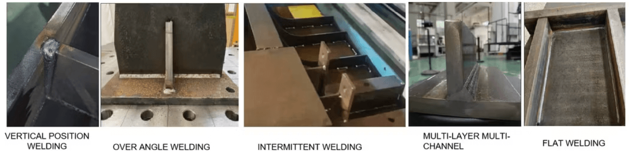
IV. Welding Robot Weld Type
V.Robot Welding Samples